

Product Features and Specifications
- General Product Information
-
 HIGH OUTPUT CAPACITY
GUARANTEED PERFORMANCE
MULTIPLE OUTPUT CAPACITIES
SIMPLE OPERATION PRINCIPLE
DESIGNED FOR EASY MAINTENANCE
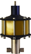
WIDE RANGE OF OPERATING PRESSURESSC Hydraulic Engineering 80-6 Intensifiers operate on the same principle as our air operated liquid pumps with one distinctive difference - the air motor is modified so that it operates as a double-acting cylinder. Instead of automatically reciprocating until the stall pressure is reached, the 80 Series Intensifiers require an external four-way air valve to operate the unit.
The end caps have 1/4" NPT air supply port connections and the unit can be supplied with a position indicator rod at the top of the intensifier if required. All ratios and options available on the intensifiers are the same as on our D5 and D6 Series pumps. The units can be mounted in any position however upright is preferred. The air cylinder does not require lubrication.
-
- Applications
-
Static and burst testing
Hydraulic Press operation
Clamping
Pressing
Metal forming
Piercing
Blanking
Staking
Flow testing requiring relatively low flows at high pressures
Applications requiring extreme intermittent pressure and velocity commonly associated with water blasting and jetting.
-
- Dimensions
-
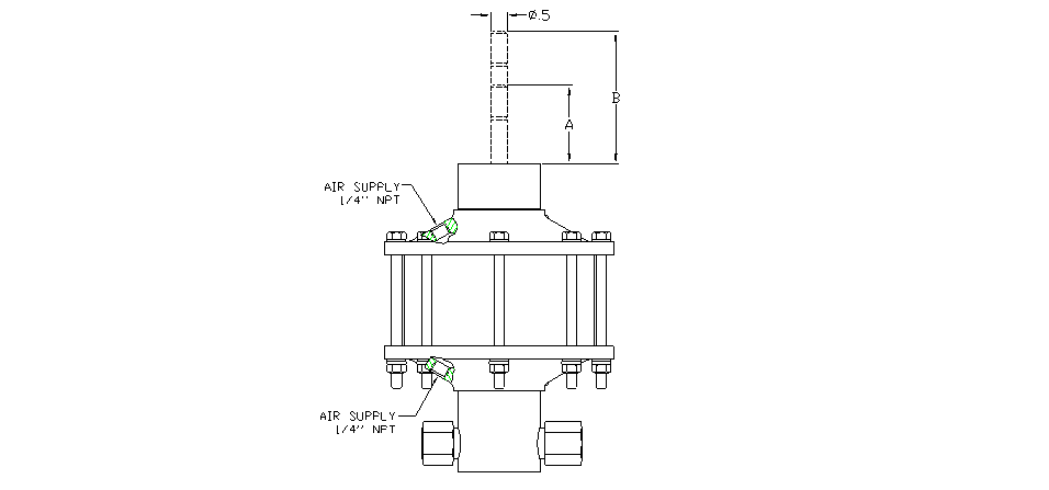
POSITION ROD INDICATOR MODEL "A" RETRACT "B" EXTEND 80-6 2.362 3.987
D6 Series
Model
(Ratio)10-6 Series
ModelL A B NPT/HF4 (Std) SAE/HF4 (Optional) E F G H C Thread D Thread C Thread D Thread 5 003 19.625 4.875 2.375 1 1/4" 1" - - 1.5 2.5 --- 4 10 005 18.625 4.75 4.375 1" 1" - - 1.375 1.375 2.375 3 20 thru 35 010 thru 020 17.063 3 4 1" 1/2" - 10 SAE 1.000 1 1.75 2.5 55 thru 180 030 thru 100 15.750 3 3.375 1/2" 1/2" 10 SAE 10 SAE 0.875 0.875 1.75 2.5 240 thru 330 151 thru 201 16.000 2.5 2.313 3/8" 3/8" - 9/16"-18 * 0.875 0.875 1.75 2.5 460 301 16 3.75 2.313 3/8" 9/16"-18 * - - 0.875 0.875 1.75 2.5 740 402 16.25 4.25 2.313 3/8" 9/16"-18 * - - 1.125 1.125 2.375 3 * Coned and threaded high pressure connection for 1/4" O.D. tubing.
D6 Series
Model
(ratio)10-6
Series
ModelHydraulic
Piston
Diameter (in)Hydraulic
Piston Area
(in2)Volume
per Stroke
(in3)Air Pressure (PSI) 10 20 30 40 50 60 70 80 90 100 5 003 3 7.07 17.7 50 100 150 200 250 300 350 400 450 500 10 005 2.125 3.56 8.9 85 185 285 390 490 590 690 795 900 1000 20 010 1.438 1.62 4.05 165 425 650 875 1075 1300 1550 1750 1950 2150 25 015 1.315 1.35 3.38 180 450 725 1000 1300 1550 1850 2125 2400 2700 35 020 1.125 0.994 2.49 250 625 1025 1400 1800 2150 2500 2850 3250 3600 55 030 0.875 0.601 1.5 450 1050 1700 2275 2900 3500 4100 4650 5200 6000 95 050 0.688 0.371 0.928 750 1750 2800 3700 4750 5900 6875 7700 8750 9700 145 080 0.563 0.249 0.623 1100 2600 4200 5550 7100 8500 10000 11500 12950 14400 180 100 0.5 0.196 0.49 1500 3200 5200 7100 9000 10800 12500 14500 16300 18000 240 151 0.438 0.15 0.375 1900 4400 6900 9100 11600 14000 16400 18800 21300 23700 330** 201** 0.375 0.11 0.275 3000 6000 9500 12600 16000 19100 22300 25600 29000 32300 460** 301** 0.313 0.077 0.193 4000 8800 13700 18000 22500 27000 31500 36500 41400 45800 740** 402** 0.25 0.049 0.123 6000 13000 21000 27000 34000 40500 46000 52000 59000 65000 ** Recommended for continuous duty at pressures up to 30,000 psi. Intermittent duty above 30,000 psi.
-
- Ordering
-
TABLE 1 Pump Series Designation (2) 80-6 7" Bore Intensifier 83-6 7" Intensifier with Position Indicator Rod TABLE 2 Seal Compound - Air Motor 0 Buna-N (standard) V Viton TABLE 3 Seal Compound - Hydraulic Section Blank Standard - No Modifications 0 Buna-N nitrile (standard) E EPR - ethylene propylene V Fluorocarbon * Consult factory for special compounds TABLE 4 Modifications 0 Standard Pump A "A" Modification B Botton Inlet C Chevron Seals D Bottom Inlet - heavy duty (3) E Bottom Inlet - "A" Modification F Isolator - Chevron Seals (3) G Isolator - heavy duty (3) H Heavy duty J Bottom Inlet - "K" modification K "K" Modification M Bottom Inlet - "A" and "K" Modification N Isolator - "A" Modification P Isolator - "K" Modification Q Isolator - "A" and "K" Modification R Isolator S Heavy duty - "K" Modification (3) U Heavy duty - bottom inlet - "K" Modification (3) V Heavy duty - isolator - "K" Modification (3) TABLE 5 Material of Construction - Hydraulic Section W Aluminum bronze & stainless steel (standard) B Aluminum bronze & stainless steel D5 Series (standard) S Stainless steel C Cad plate carbon steel, stainless steel (1) TABLE 6 Model Designation - Pressure Ratio Refer to pressure ratio charts for proper selection TABLE 7 Port Option Blank Standard Pump SAE Straight thread as indicated on chart HF4 9/16-18 x 1/4" OD tube 60K psi Additional modifications may be included with an "M" suffix at the end of the model number.
Notes: (1) 25 piece minimum order (2) Do not fill gap on a two digit description. (3) "A" modification included with all Chevron and Heavy Duty seal modifications.
-
- Modifications
-
A Models:These models utilize dual seals in the hydraulic assembly with a bleed-off between the seals to atmosphere, thus providing a visual indication of hydraulic seal leakage. Used where contamination of the air motor from the hydraulic fluid being pumped is objectionable.

B Models:The "B" models have a bottom inlet connection for convenient tank top installation or alternate mounting configuration.

C Models: The "C" Models utilize PTFE chevron packing in the hydraulic assembly for ultimate performance when other packing material is not compatible with the fluid used or because of extreme temperature conditions. The "A" modification is included on all "C" models and the check valves have PTFE o-rings.
H Models:The "H" Models utilize special packing in the hydraulic assembly for maximum performance where hydraulic fluid media is contaminated with foreign matter, thus providing for a much greater life expectancy from the hydraulic seals than with standard o-ring seals. The "A" modification is included on all "H" models and the check valves have PTFE o-rings.

K Models:This models utilize a special air piston in the air motor assembly which decreases the stroke of the pump, thus minimizing the internal forces and increasing air motor life. Used in applications exhibiting rapid pressure losses, such as burst testing.
R Models:The "R" Models are furnished with an isolator attachment which prevents the hydraulic piston retracting into the air motor during operation, thus providing for 100% non-contamination of the hydraulic assembly from the air motor. The isolator also acts as a heat barrier.

-
- Performance Chart
-


Product categories
Request a Quote