

Product Features and Specifications
- General Product Information
-
 OIL SERVICE ONLY
AUTOMATIC OPERATION
COMPONENTS INSTALLED ON A BASE PLATE
AVAILABLE WITH 10-5 AND 10-6 SERIES PUMPS
INCLUDES THREE GALLON PRESSURIZED RESERVOIR
HIGH-SPEED LOW-PRESSURE OR LOW-SPEED HIGH-PRESSURE OPERATIONThe 50 Series is a self-contained unit complete with a three gallon pressurized reservoir, hydraulic pressure unloading valve, air sequence valve and manual air control valve. It is designed for oil service only.
This unit provides high-speed low-pressure operation and low-speed high-pressure operation automatically.
Only two positions of the control valve are required for a complete cycle of operation. When the control valve is shifted (see circuit below), air pressure is applied to the reservoir. This pressurization initiates free flow through the pump, thus providing the high-speed, low-pressure cycle.
Upon reaching a set hydraulic output pressure, the sequence valve automatically operates the pump, thus providing the low speed high-pressure cycle.
Operation of the pump only when increased pressure is required saves air, assures maximum pump life, and reduces operating and maintenance costs.
Opposite position of the control valve activates the pressure unloading valve and dumps system pressure back to the reservoir.
Design of the unit permits the use of the air supply for return cycle if needed. The unit is easily converted for semi or fully automatic operation.
-
- Applications
-
Pressing
Clamping
Static and burst testing
Hydraulic press operation
Cylinder extension requiring rapid initial actuation
-
- Dimensions
-
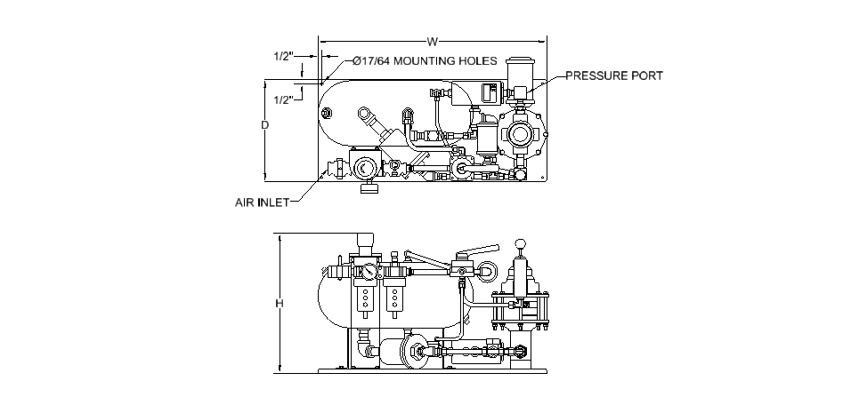
Model No.
Standard10 Series Hyd
Section CodePump Ratio Overall Dimensions (in) Ports NPT N.C. Pressure
Release ValveW D H Air Drive Pressure 50-5 Series 005, 007 10:1, 12:1 25 12.5 16.5 1/2" 1/2" PRC-100-N-050 010 20:1 015 25:1 3/8" 018, 020 30:1, 35:1 030, 040 55:1, 70:1 045 85:1 060 105:1 080 140:1 1/4" PRC-200-N-050 080-HF4 140:1 100 195:1 100-HF4 195:1 160 280:1 PRC-300-N-HF9 160-HF4 280:1 50-6 Series 010 20:1 28 12.5 19.44 1/2" 1/2" PRC-100-N-050 015, 020 25:1, 35:1 030 55:1 3/8" 050 95:1 080 145:1 PRC-200-N-050 100 180:1 1/4" 151 240:1 PRC-300-N-HF9 151-HF4 240:1
-
- Ordering
-

TABLE 1 Power Unit Designation (4) 5 50 Series TABLE 2 Reservoir Option * Three gallon for oil service only TABLE 3 Pump Series Designation 4 10-4 Series 5 10-5 Series 6 10-6 Series TABLE 4 Seal Compound - Air Motor 0 Buna-N nitrile (standard) V Viton TABLE 5 Seal Compound - Hydraulic Section 0 Buna-N nitrile (standard) E EPR - ethylene propylene V Fluorocarbon * Consult factory for special compounds TABLE 6 Modifications 0 Standard pump A "A" modification B Bottom inlet (1) D Bottom inlet - heavy duty E Bottom inlet - "A" modification (1) G Isolator - heavy duty (1,3) H Heavy duty (1) J Bottom inlet - "K" modification (1) K "K" modification (1) M Bottom inlet - "A" and "K" modification (1) N Isolator - "A" modification (1) P Isolator - "K" modification (1) Q Isolator - "A" and "K" modification (1) R Isolator (1) S Heavy duty - "K" modification (1,3) U Heavy duty - bottom inlet - "K" mod. (1,3) V Heavy duty - isolator - "K" modification (1,3) TABLE 7 Material of Construction - Hydraulic Section W Aluminum bronze & stainless steel S All stainless steel C Cad plate carbon steel, stainless steel (2) TABLE 8 Pressure ratio model designation Refer to pressure ratio charts for proper selection
Use suffix "L" if lube style pump is included, leave blank for non-lube "Dry Seal" typeTABLE 9 Port option Blank Standard SAE Straight thread as indicated on chart HF4 9/16-18 x 1/4" OD tube 60K psi Notes: (1) Do not fill gap on a two digit description (2) 25 piece minimum order (3) "A" modification included with all "H" modifications (4) Do not fill gap on a two digit description
-
- Modifications
-
A Models:These models utilize dual seals in the hydraulic assembly with a bleed-off between the seals to atmosphere, thus providing a visual indication of hydraulic seal leakage. Used where contamination of the air motor from the hydraulic fluid being pumped is objectionable.

B Models: The "B" models have a bottom inlet connection for convenient tank top installation or alternate mounting configuration. 
H Models: The "H" Models utilize special packing in the hydraulic assembly for maximum performance where hydraulic fluid media is contaminated with foreign matter, thus providing for a much greater life expectancy from the hydraulic seals than with standard o-ring seals. The "A" modification is included on all "H" models and the check valves have PTFE o-rings. 
K Models: This models utilize a special air piston in the air motor assembly which decreases the stroke of the pump, thus minimizing the internal forces and increasing air motor life. Used in applications exhibiting rapid pressure losses, such as burst testing. R Models: The "R" Models are furnished with an isolator attachment which prevents the hydraulic piston retracting into the air motor during operation, thus providing for 100% non-contamination of the hydraulic assembly from the air motor. The isolator also acts as a heat barrier.
-
Product categories
Request a Quote