

Product Features and Specifications
- General Product Information
-
 EASY TO INSTALL
PRESSURES UP TO 65,000-PSI
COMPACT AND LIGHTWEIGHT
INCLUDES RETURN-TO-RESERVOIR LINE
COMPONENTS INSTALLED ON A BASE PLATE
AVAILABLE WITH ALL 10-SERIES PUMP MODELS
INCORPORATES OPTIONAL TWO OR THREE GALLON RESERVOIRThe 40 Series incorporates a larger base plate than the 30 Series to accommodate an optional two or three gallon reservoir.
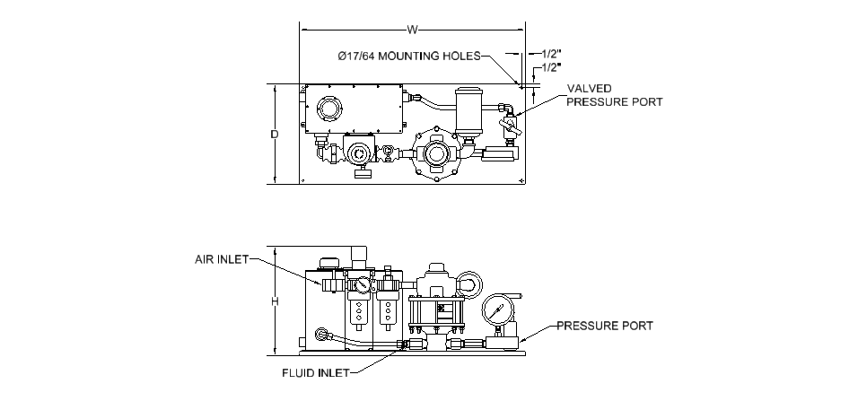
Light weight, easy to install. Only three connections are required; air, fluid supply, and work port.
Two pressure ports, one equipped with shut-off or bleed valve, provide ease of control during operation. Valve connects to reservoir when so equipped.
Air exhaust muffler provides for quiet operation, 3 1/2" dial liquid filled gauge standard on units up to 30,000 psi.
-
- Applications
-
Staking
Piercing
Pressing
Blanking
Clamping
Flow testing
Metal forming
Static and burst testing
Hydraulic press operation
-
- Dimensions
-
Model No.
Standard10 Series Hyd
Section CodePump Ratio Gauge
PressureOverall Dimensions (in) Ports NPT W D H Air Drive Fluid Supply Pressure 40-4 Series 003 5:1 0-1,000 21 12 12.25 1/4" 1/2" 3/8" 005 10:1 0-2,000 010 15:1 0-3,000 9.25 3/8" 1/4" 015, 020 30:1, 35:1 0-6,000 030 55:1 0-10,000 8.75 050 100:1 0-15,000 080 140:1 0-20,000 125 220:1 0-30,000 40-5 Series 003 5:1 0-1,000 28 12.5 15.75 1/2" 1" 1/2" 005, 007 10:1, 12:1 0-2,000 010 20:1 0-3,000 015 25:1 0-5,000 13.5 1/2" 3/8" 018, 020 30:1, 35:1 0-6,000 030, 040 55:1, 70:1 0-10,000 045 85:1 0-15,000 060 105:1 0-15,000 1/4" 080 140:1 0-20,000 14 3/8" 080-HF4 140:1 0-20,000 9/16"-18 * 100 195:1 0-30,000 1/4" 100-HF4 195:1 0-30,000 9/16"-18 * 160 280:1 0-30,000 1/4" 160-HF4 280:1 0-30,000 9/16"-18 * 250 440:1 No Gauge ** 1/4" 250-HF4 440:1 No Gauge ** 9/16"-18 * 350-HF4 555:1 No Gauge ** 9/16"-18 * 40-6 Series 003 5:1 0-1,000 28 12.5 20.25 1/2" 1 1/4" 1" 005 10:1 0-2,000 1" 010 20:1 0-3,000 17.5 1/2" 015, 020 25:1, 35:1 0-6,000 030 55:1 0-10,000 16.5 1/2" 3/8" 050 95:1 0-15,000 080 145:1 0-20,000 100 180:1 0-30,000 1/4" 151 240:1 0-30,000 16.75 3/8" 151-HF4 240:1 0-30,000 9/16"-18 * 201 330:1 No Gauge ** 1/4" 201-HF4 330:1 No Gauge ** 9/16"-18 * 301-HF4 460:1 No Gauge ** 17 9/16"-18 * 402-HF4 740:1 No Gauge ** 9/16"-18 * * Coned and threaded high pressure connection for 1/4" O.D. tubing.
** Consult factory if gauge is desired.
-
- Ordering
-
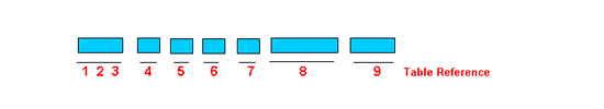
TABLE 1 Power Unit Designation (4) 4 40 Series TABLE 2 Reservoir Option 0 No Reservoir 2 Two Gallon 3 Three Gallon TABLE 3 Pump Series Designation 4 10-4 Series 5 10-5 Series 6 10-6 Series TABLE 4 Seal Compound - Air Motor 0 Buna-N nitrile (standard) V Viton TABLE 5 Seal Compound - Hydraulic Section 0 Buna-N nitrile (standard) E EPR - ethylene propylene V Fluorocarbon * Consult factory for special compounds TABLE 6 Modifications 0 Standard pump A "A" modification B Bottom inlet (1) D Bottom inlet - heavy duty E Bottom inlet - "A" modification (1) G Isolator - heavy duty (1,3) H Heavy duty (1) J Bottom inlet - "K" modification (1) K "K" modification (1) M Bottom inlet - "A" and "K" modification (1) N Isolator - "A" modification (1) P Isolator - "K" modification (1) Q Isolator - "A" and "K" modification (1) R Isolator (1) S Heavy duty - "K" modification (1,3) U Heavy duty - bottom inlet - "K" mod. (1,3) V Heavy duty - isolator - "K" modification (1,3) TABLE 7 Material of Construction - Hydraulic Section W Aluminum bronze & stainless steel S All stainless steel C Cad plate carbon steel, stainless steel (2) TABLE 8 Pressure ratio model designation Refer to pressure ratio charts for proper selection
Use suffix "L" if lube style pump is included, leave blank for non-lube "Dry Seal" typeTABLE 9 Port option Blank Standard SAE Straight thread as indicated on chart HF4 9/16-18 x 1/4" OD tube 60K psi Notes: (1) Do not fill gap on a two digit description (2) 25 piece minimum order (3) "A" modification included with all "H" modifications (4) Do not fill gap on a two digit description
-
- Modifications
-
A Models:These models utilize dual seals in the hydraulic assembly with a bleed-off between the seals to atmosphere, thus providing a visual indication of hydraulic seal leakage. Used where contamination of the air motor from the hydraulic fluid being pumped is objectionable.

B Models: The "B" models have a bottom inlet connection for convenient tank top installation or alternate mounting configuration. 
H Models: The "H" Models utilize special packing in the hydraulic assembly for maximum performance where hydraulic fluid media is contaminated with foreign matter, thus providing for a much greater life expectancy from the hydraulic seals than with standard o-ring seals. The "A" modification is included on all "H" models and the check valves have PTFE o-rings. 
K Models: This models utilize a special air piston in the air motor assembly which decreases the stroke of the pump, thus minimizing the internal forces and increasing air motor life. Used in applications exhibiting rapid pressure losses, such as burst testing. R Models: The "R" Models are furnished with an isolator attachment which prevents the hydraulic piston retracting into the air motor during operation, thus providing for 100% non-contamination of the hydraulic assembly from the air motor. The isolator also acts as a heat barrier.
-
Product categories
Request a Quote